Circuit Diagram Full Wave Center Tap Rectifier Unregulated F
Si lab Full-wave center-tap rectifier Full tap wave center rectifier circuit diagram experiments schematic circuits connection switch half between close open will
Electrical – Efficiency of a centre tap full wave rectifier(qualitative
Rectifier wave full center tapped circuit circuitlab description Electrical – efficiency of a centre tap full wave rectifier(qualitative Wave controlled full center tap rectifier circuit rectifiers figure
Full wave rectifier
Center rectifier tap wave fullRectifier voltage waveform circuits ground [diagram] wiring diagram for rectifier and capacitorCenter tapped full wave rectifier.
Electronic – ground in the circuit of full wave rectifier – valuableFull-wave center-tap rectifier Full wave rectifier op circuitFull-wave center-tap rectifier : discrete semiconductor circuits.

Draw circuit diagram of a full wave rectifier
Rectifier wave tapped full center voltage peak operation inverse diagram circuit opto proteus signal bidirectional simulate isolators itsFull rectifier circuit diagram Rectifier circuits learningelectronicsFull wave rectifier png.
Wave full rectifier tapped center working animation half positive operation gif voltage dc d1 engineering rectified biased resistor tutorial engineeringtutorialCenter tapped full wave rectifier circuit diagram Centre tap full wave rectifier circuit diagram in 2021 circuitFull wave rectifier.
![[Solved] Explain the operation of a FULL wave Center Tap wave rectifier](https://i2.wp.com/www.coursehero.com/qa/attachment/32466661/)
What is full wave rectifier circuit diagram working advantages
Center-tapped full-wave rectifier operation -…Rectifier wave full circuit bridge voltage output working transformer tapped centre across load advantages consists Circuit diagram of centre tap rectifierRectifier wave full tap centre waveforms diagram circuit waves waveform circuits electronics.
Full wave rectifier basics, circuit, working & applicationsRectifier tapped voltage peak Centre tap full wave rectifier circuit operation,working,diagram,waveform[diagram] wiring diagram for rectifier and capacitor.

Center tapped full wave rectifier operation
Center tapped full wave rectifier : circuit, working & applicationsCenter tapped full wave rectifier circuit diagram Full-wave controlled center-tap rectifiersRectifier tapped.
Full wave controlled rectifier circuit diagram[solved] explain the operation of a full wave center tap wave rectifier Centre tap full wave rectifier circuit operation,working,diagram,waveformFull-wave center-tapped rectifier tutorial.

Full wave rectifiers
Draw the circuit diagram of a full wave centre tap rectifier with rlFull wave bridge rectifier circuit diagram .
.


Full Rectifier Circuit Diagram

Electrical – Efficiency of a centre tap full wave rectifier(qualitative

What Is Full Wave Rectifier Circuit Diagram Working Advantages - Riset

Full Wave Rectifier PNG

Draw Circuit Diagram Of A Full Wave Rectifier
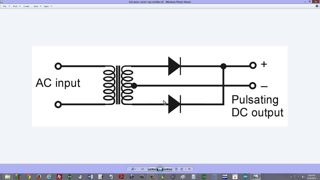
Full-Wave Center-Tap Rectifier - YouTube
![[DIAGRAM] Wiring Diagram For Rectifier And Capacitor - MYDIAGRAM.ONLINE](https://i2.wp.com/electric-shocks.com/wp-content/uploads/2019/03/Full-wave-Center-tapped-rectifier-circuit-diagram.jpg)
[DIAGRAM] Wiring Diagram For Rectifier And Capacitor - MYDIAGRAM.ONLINE